https://www.bulksolids.nl/bulk_technology.html
BSE bulk solids engineering Tel.: +31 53 434 45 66
Print: 27 Apr 2024 07:45
BSE bulk solids engineering Tel.: +31 53 434 45 66
Print: 27 Apr 2024 07:45
Bulk technologyBulk solids properties, silo design, screw feeder designBelow is a compilation of several articles on bulk technology that describe the basics of silo design. C O N T E N T S
Flow from silos does not happen by itself
Flow characteristics should be the basis of any design
Bulk handling development; Silo geometry, Slim silos, Mammoth silos, Flat bottom silos; Flow pattern, Mass flow, Core flow; Funnel flow; Hopper shapes, Axial symmetric flow, Flat symmetric flow, Funnel angle; Flow problems, Arching, Bridging, Shaft building, Time consolidation. Silo design; Mass flowObjective: mass flow by gravity in a simple silo
Silo design is customisation; Flow pattern, Mass flow; Influences flow pattern, Procedure mass flow design; Design on bridging, Congestion of large chunks, Cohesive bridge formation, Flow - No Flow, Strength of the bridge, Procedure for bridging; Flow promotion (flow promotors), Bridge breakers, Screw feeder, Dosing screw, Guidelines for discharge devices. Silo design and product consolidationThe influence of time consolidation
Monday morning problems; Time flow function; Outlet opening after standstill; Design with standstill, Elimination of consolidation, Discharge bottom, Preventing consolidation; Product consolidation and flow pattern; Influence of withdrawal device; Bridge formation in cylinder Silos with core flowFlow channel is in product itself at core flow silo
Core flow versus mass flow; Smaller construction height; Avoid stable shaft formation, upper limit stable shaft formation, lower limit stable shaft formation; Check on bridging; Hopper angle for emptying; Extended flow hopper; Flat bottom silos or stockpiles Problem-free dosing with a dosing screwDesign based on minimum pitch, core diameter and pitch gradient
Screw feeder; Operating principle of screw conveyors; Optimal screw transport; Minimum pitch; Design of screw feeder; Drive power Document: Phenomena in silosPressure build-up, product breakage, silo quaking, segregation
Discusses phenomena that can cause problems when storing bulk materials in silos. Including solution directions and some practical cases. Flow from silos does not happen by itselfFlow characteristics should be the basis of any designOver time, the storage silo became more sophisticated. This brought the necessary headaches. Storage requires more than putting it in a silo and taking it out in due course. Below is a description of different designs of storage silos, problems that can occur and possible solutions. Development of bulk technologyThe art of bulk storage is almost as old as mankind itself, because much of the food stock harvested or gathered during the warm season had to be stored in some way to get through the winter. This was initially done in holes in the ground, or in some kind of huts or caves. Later followed the man-made earthenware vessels where the bulk food, usually a grain, was inserted from above and at a later stage could be scooped out through the same opening. Such a grain silo is sometimes still used today at small farming communities in Africa. Problems do not often occur with this type of storage: It involves familiar products in a simple and reliable storage system. With storage systems as we encounter them in our industrialised world, things are a bit more complicated. They sometimes even turn out to be the bottleneck in the production process. 
Silo geometry
The most commonly used silo consists of a cylindrical upper part;
round, square or rectangular, and a funnel-shaped outlet part; a cone, or a shape composed by sheet metal parts.
The storage product enters the silo from the top using a pneumatic or mechanical conveying system.
At the bottom of the silo, the required quantity can be withdrawn again. The flow through the silo takes place by gravity. Sometimes assisted by flow aids.
Slender silos
When the ratio (H/D) is greater than two, one speaks of slender silos.
In practice, most slender silos have a diameter of 2 to 4 m, but diameters of 10 m also occur.
The storage capacity is in the range of 10 to 300 cubic metres.
Mammoth silos, flat bottom silos
In contrast to slender silos are the so-called flat-bottomed or mammoth silos (squat silos).
The latter type of silo usually consists only of vertical walls, the funnel is missing or is very flat.
The height-to-diameter ratio of this type of silos is usually less than 1.
The cylinder diameter can be as much as 60 metres. Storage capacities are between 1,000 and 100,000 cubic metres.
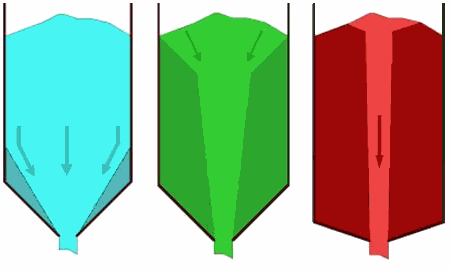
Flow pattern
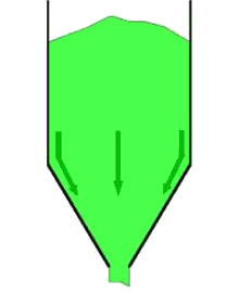
With regard to flow of bulk solids in a silo, two main types of flow can be distinguished: mass flow and core flow. Mass flowIn mass flow, the entire mass in the silo moves at the moment bulk material is extracted from the silo. There is "first-in, first-out" (FiFo). Although small speed differences may occur, there are no stationary zones. Because flow takes place across the entire cross-section of the silo, flow velocities are relatively low, creating a regular flow that is easily controllable. This type of flow is characterised by:
Disadvantages of mass flow may be that shocks may occur in specific cases. For abrasive products, the silo walls will wear more. However, due to the low flow rates in a silo, this is usually not a problem. Using Jenike's theories, it is possible to determine for different funnel shapes what type of flow pattern will occur. Core flowIn core flow, the product at the wall initially remains at rest and flow takes place through a funnel or channel formed in the product itself above the outlet. This channel is refilled from above from the stagnant areas. Here, of course, there is no first-in, first-out. The flow is less regular due to the sometimes jerky collapse of the dead zones. 
With core flow, the following problems can arise:
Core flow is therefore only applicable for coarse, free-flowing products where decay or ageing does not play a role. What type of flow will occur in a silo depends on the internal friction of the product, the friction between product and silo wall, and the steepness and geometry of the outlet funnel. The steeper the funnel, the higher the probability of mass flow. Using Jenike's theories, it is possible to determine for different funnel shapes what type of flow pattern will occur. Hopper shapesThe hopper angle at which mass flow still occurs can be calculated for a given hopper shape if the internal friction and wall friction are known. In terms of hopper shape, there are two main groups:
Axial symmetric flowIn round hoppers (cones), rectangular (pyramid-shaped) hoppers, so-called axial symmetric flow occurs. Here, the product must converge through an axisymmetric cross-section (round) or in two directions (rectangular). .png "Examples of round hoppers")

Plane strain flowIn a wedge-shaped funnel, constriction occurs only in one direction, this is called plain strain flow. The bulk material experiences less resistance when flowing out, resulting in mass flow already occurring at a less steep angle. 
In practice, mass flow is usually preferred to core flow, mainly because of the advantage first-in, first-out. A disadvantage of mass flow is that the contents slide along the silo wall, resulting in wear. Because of the low velocities in the silo, in practice this only causes problems with very abrasive products (hard products) or products contaminated with hard particles. Hopper angle
Furthermore, the required height of the funnel deserves attention. In case of problems, intermediate solutions can approximate mass flow as closely as possible so that a less high funnel will suffice.
The sometimes heard remark that mass flow will always occur at a funnel angle of 30 degrees to the vertical (60 degrees to the horizontal; i.e. a top angle (enclosed angle) of 60 degrees) unfortunately does not always hold true.
This shows that for axial-symmetric flow, at a cone angle of 30 degrees to the vertical, mass flow will occur in only a quarter of the combinations studied. For plane flow, the curve shifts eight to 10 degrees to the right (not shown), so mass flow will occur in about half of the cases. Flow problemsArching/BridgingWhen designing a silo, in addition to the flow pattern, the possible occurrence of bridge formation or shaft formation must be taken into account. In a silo with mass flow, the main source of interference is the occurrence of more or less stable bridges that disrupt or completely stop the flow. For large bulk solids, this will involve mechanical wedging of some particles above the outflow opening. This can be prevented by choosing the outlet diameter seven to nine times larger than the largest chunks of product. 
bridges.gif)
In powders and in bulks solids with a proportion of small particles, bridging occurs due to cohesion.
Due to the cohesion between a large number of particles, a stable dome can form.
This can occur in the cylinder (the part with vertical walls), but usually bridging occurs in the hopper.
Based on the product properties (flow properties, flow characteristics) and silo theory, a minimum outlet size can be chosen at which stable bridge formation will not occur.
Time consolidation
Storage time also plays a role. Bridging in the cylinderHowever, circulating the contents of the silo from time to time does not help against consolidation in the cylinder (the vertical part). This is because the bulk solids particles do not have to move relative to each other there; the mass can slide down as a single block of material.If the product reinforcement is large, and/or the silo diameter is relatively small, the strength of the bridge can become so large that the span of a stable bridge becomes larger than the silo diameter. At that point, a stable bridge can remain in the cylinder. This is usually at the transition from cylinder to hopper. In square silos made with horizontally corrugated walls, or when there is a ledge or edge present in the cylinder, a bridge can find support at a higher level in the silo. Collapse of a bridge from such a location can cause a lot of damage due to the impact (the hopper can collapse in one blow). Shaf buildingIn the case of core flow, the main problem is the occurrence of a stable flow channel that can empty while the rest of the product is not moving. Again, based on product properties and theory, a minimum opening can be chosen that avoids this stable shaft formation. In addition, of course, stable bridge formation in the occurring flow channel must be avoided. A proper design is bespoke; it weighs the actual properties of the product with the conditions under which it is stored. Silo design for mass flowObjective: mass flow by gravity in a simple siloThe classic method of designing silos is discussed below, using the most common type of silo, which consists of a vertical cylindrical top section with a discharge hopper underneath. The main requirement in the design is that undisturbed mass flow should occur. Silo design is tailor-made
Designing a silo is much like the work of a good tailor.
Just as the latter has to know the requirements and wishes of the client who will wear his creation, the silo designer will also have to start from the user's requirements.
And where the tailor needs to accurately measure the measurements of his client, the silo designer also needs to know (or measure) the properties of the product that will be stored.
In short, silo construction is also mostly customised. With mass flow, all the product in the silo will be in motion and therefore no dead zones will occur. Furthermore, the product that enters the silo first is also the first to flow out, the so-called first in - first out principle (FiFo). Furthermore, little segregation will occur in the silo and there is a regular and well-controllable outflow. Because of these favourable characteristics, mass flow will be chosen in many cases. Especially when spoilage, unwanted mixing or ageing of the stored product play a role. Flow patternThe type of flow that will occur in a silo is determined by the behaviour of the bulk material in the outlet hopper. If the product in the entire hopper flows along the wall, this will also happen in the rest of the silo and we speak of pure mass flow. If the product in the hopper does not flow or only partly flows along the wall, this will also apply to the rest of the silo. In that case, a localised form of mass flow may occur higher up in the cylinder, but stagnant or poorly flowing areas will occur deeper in the silo. With all its drawbacks. The flow behaviour of the bulk material in the hopper is mainly determined by the 1) steepness of the hopper and 2) the friction between product and wall material. In the determinations of the flow pattern, the hopper angle with the vertical (alpha) is used. The wall friction is expressed as the angle (phiW) between the x-axis and the wall yield locus, or as a coefficient (mu = tan(phiW) ). The internal friction of the bulk material plays a minor role. Mass flow
In classical silo theory as developed by A.W. Jenike and others, it has been deduced for which combinations of alpha and phiW
mass flow will occur, for various values of internal friction.
The diagrams below show this for two types of flow: axial-symmetric flow and plane flow.

The graphs show that the internal friction angle of the bulk material (indicated by phiE) also has a small influence. So when the wall friction angle phiW between the bulk material and the intended wall material is known (it will have to be measured), the hopper angle alpha can be chosen such that mass flow will occur. This applies to both free-flowing and cohesive materials. In the case of axi-symmetric flow, a cone angle that is about 3° steeper than the found limit is usually chosen in practice. This is to compensate for any deviation in phiW. For plane strain flow, the limit value is less strict and (depending on the situation) no safety margin is needed. In practice, it has been found that (especially for plane strain flow) mass flow can also occur at less steep cone angles with sufficient filling height of the bulk material in the cylinder. Silo design usually does not take this into account and chooses values that lead to mass flow even at smaller filling heights. Influences of flow patternIn the vast majority of cases, mass flow is desired. Therefore, it pays to design the silo to ensure this type of flow. The flow pattern that occurs in a silo is determined by:
Here, it can be generally stated that mass flow is promoted by a steeper and smoother hopper. The walls and corners should therefore be smooth. Furthermore, a hopper with a slotted opening is better than a round or square hopper. Procedure mass flow designDesign of a mass flow hopper is as follows:
Design for arching/bridging (flow)The fact that mass flow occurs at a well-chosen inclination angle of the hopper does not mean that flow will occur in all cases. If the opening is too small, bridging will occur, so there will be no flow at all. So after choosing the appropriate hopper angle, a suitable outlet opening must now be chosen. The main cause of problems in mass flow is the formation of more or less stable bridges that will hinder or even stop the flow altogether. 
Jamming of large particlesFor (coarser) bulk solids, larger particles can get mechanically jammed directly above the opening. By choosing the smallest size of this opening at least five or seven times larger than the largest product particles, this is prevented. Cohesive arching/bridging
In the case of cohesive products, this involves the fusion of many particles that can lead to stable domes or bridges.
In this case, simple rules of thumb will not get us there, but a closer look is needed.
For this, see the figure below, where the factors involved in bridge formation in a silo are plotted.
As a result of this stress sigma1, the (cohesive) material acquires a certain unconfined yield strength sigmaP, which depends on the size of sigma1. Think, for example, of a snowball: the harder we squeeze it, the stronger it becomes. We can think of the unconfined yield strength sigmaP as the resistance to deformation offered by the material in question. This strength depends on the location in the silo.
Next, we consider the product in the silo (or rather mainly in the hopper) as if it were composed of a series of superimposed placed
bridges or arches that are supported by the silo wall, where each arch carries at least its own weight.

Flow – No FlowFrom the classical silo theory, it follows that the ratio between consolidation stress sigma1 and the required bridge strength sigma1' for a given combination of bulk material and silo hopper (represented by alpha, phiW and phiE) has a constant value. This factor is called the flow factor (ff). Plotted on a graph, this thus produces a straight line, at a certain angle to the x-axis. This value can be calculated from theory or read graphically for a specific case. The relationship between consolidation stress sigma1 and own strength sigmaP, depends purely on the bulk material and should be measured with a suitable tester. This relationship is referred to as Flow Function FF. Both lines are plotted in the figure, and again, a bridge is not stable as long as the required bridge strength (ff) is greater than the material strength (FF), which is the case to the right of the intersection of the two lines. The intersection of ff and FF indicates where the situation is critical. From the corresponding critical value of sigma1', the corresponding critical outlet of the hopper Dcr can be calculated directly. In practice, we usually choose a surcharge of 25% on this for the actual minimum opening to be applied. Strength of the bridge
The product in the silo will experience pressure from the product above. This silo pressure gives the product a certain cohesion, its own strength.
Compare this to forming a snowball and a "sand ball"; the latter is not possible with dry sand.
Especially the latter plays a role in many situations, as often evidenced by start-up problems after a weekend.
This is caused by consolidation.
To calculate the strength of a bridge, its own strength as a function of pressure must be measured.
Design for bridgingThis part of the silo design involves determining the diameter of the opening to allow the product to flow out problem-free. The procedure is as follows:
Sometimes the opening required for flow is too large to be practical. Using the available data, a targeted solution can be sought:
Thus, depending on the situation, the optimum solution can be found with the design method and supporting tests. Flow promotion
Sometimes the required discharge opening is very large. For products with low bulk density and high cohesiveness or stickiness, bridging can occur (after standstill) up to several metres of span.
For light, sticky products, 3 to 5 metres is no exception. There have even been cases of bridges with a span of 9 metres.
In this situation, the product was extracted by a 5-metre sliding framework moving back and forth. However, the hopper was empty up to a diameter of 9 metres.
If a larger critical diameter is found than a practically applicable opening then a solution will have to be found. There are broadly two options:
Bridge breakers
There is a host of bridge breakers, flow promotion devices on the market. As the saying goes: you name it, it has already been invented (and applied).
Bridge breakers are often used on existing silos, where (after standstill) it appears that the bulk material does not flow out. Adjusting the hopper shape, the hopper angle or the outlet opening is then either not possible or very expensive. It is then relatively easy to install a flow promoter, especially if this can be done on the outside of the silo. Note: when using vibrators to break possible bridges, vibration should only be used when product can flow out. Otherwise, the situation may actually worsen as the vibrations further consolidate the product. Discharge bottoms, live bottoms
Another way to ensure flow is to use a discharge bottom, which has the minimum outlet opening. Here, the size of the bottom, or moving part, is the measure of the opening the bulk material "sees". The opening underneath the bottom can then be significantly smaller.
Discharge devices
Hopper shape and inclination angle were discussed above. For the desired mass flow, the hopper geometry must be good.
However, it is not enough; another requirement is that the flow is not disturbed by underlying obstacles or equipment.
Guidelines for feeder equipment
Although there is no all-encompassing theory for this equipment, it is possible to give a few points to consider when designing and sizing.
Screw feeder, dosing screw
It was discussed above that a wedge-shaped funnel is favourable for the occurrence of mass flow.
The disadvantage is that it creates a slotted opening, which places additional demands on the discharge equipment.
This equipment must provide uniform extraction.
If this is not the case, the feeder will cause core flow, even if the silo is designed for mass flow.
Silo design and product consolidationThe influence of time consolidationThe previous chapter dealt with a standard method for designing mass flow silos. In doing so, a number of issues influencing the design or use of the silo have not yet been addressed. In this chapter, we address these and indicate how they can be taken into account in design or operation. Monday morning humour
Some storage silos seem to suffer from a Monday morning humour. On Friday afternoon, things are still running smoothly, but when restarted on Monday morning after a weekend of standstill, no product comes out of the silo. Only a few sharp blows with a sledgehammer on the hopper then sometimes get the flow going again.
Time flow functionWhile we previously indicated the measured relationship between consolidation stress (sigma1) and unconfined yield strength (sigmaP) with the flow function FF, the influence of time is shown with the time flow function FFt. The duration of undisturbed storage is also important here, as a longer time will usually lead to greater strength. Thus, for time-sensitive products, we will need to have an impression already at the silo design stage as to whether and how long the product will be stored without extracting product from the silo. 
Outlet opening after standstill
In practice, after a period of standstill, the strength of the product will usually be greater. This is reflected in the flow function, see figure above.
Shown is the flow factor (green) and the flow function without standstill (blue).
The intersection of the two lines leads to the critical value of the bridge strength,
from which the critical discharge opening d_cr0 is calculated. See design to avoid bridging.
Design with standstill
Thus, by choosing a larger outflow opening, we can take into account the time effect and the silo will restart smoothly even after standstill.
However, it is usually not possible or practical to choose the outlet opening that large. Sometimes an outlet opening would have to be so large that connection to underlying pipes or equipment would be impossible. In other cases, the large flow rate that the required outlet opening would provide may be too large for the process. In all these cases, a different approach is preferable.
Breaking consolidationThe first possibility is to assume a realistic outlet opening, e.g. the outlet opening required if the product is not stationary and reinforced with a safety allowance. We then accept that stable bridging after standstill may occur across the outlet opening, and apply a suitable tool (e.g. a vibrator, knocker, air injection or air cannon) to break these bridges. Once flow occurs, sufficient deformation takes place in the product to cancel the time influence so that further flow will occur without aids. Discharge bottom
Another way to ensure flow is to use an discharge bottom. The diameter of the bottom, or moving part, should then be as large as the required outlet opening.
When the bottom is in operation, it should discharge the bulk material over the entire surface. Whether this really works for a particular product may have to be tested in practice.
Avoiding consolidationAnother possibility is to start from the critical outlet opening, corresponding to a certain time period, e.g. six hours of undisturbed storage time, and ensure that longer periods of standstill do not occur. To do this, a relatively small amount of product (as a rule of thumb: half a hopper capacity) should be withdrawn and recirculated (or discharged) each time before six hours of standstill is reached. Flow cancels out consolidation, and so can continue without aids. Which of these options is preferable will vary from situation to situation but can be assessed based on the time influence on the product in question to be measured. See also flow promotion. Product consolidation and flow patternProduct consolidation during standstill will generally not affect the flow pattern. When the flow is restarted, with or without aids, the same flow pattern will occur. Only in exceptional situations, for example when during standstill the product really cakes to the wall or forms permanent lumps, problems may occur. This caking behaviour usually becomes apparent during measurements in the design phase. Choosing a different wall material, for instance stainless steel or a suitable coating, may be a solution. Influence of discharge mechanism
Directly below the discharge opening of a silo is usually a discharge mechanism (feeder). This is a short conveying device that controls the flow of product out of the silo. Screw, belt and vibratory feeders are commonly used. For proper silo operation, it is important that the feeder extracts product over the entire outlet opening.

Practice case screw feeder
A silo for wood and gypsum powder regularly gave flow problems.
This manifested itself in stagnation of the flow. Beneath the silo a screw feeder with a varying pitch was installed.
Checking the design of the silo revealed that mass flow should occur in the silo.
Bridging in the cylinder
Bridging does not only occur in the hopper. Sometimes, more or less stable domes also form in the cylinder/the vertical part of the silo.
This is most often due to time consolidation. When the product under the dome does flow out normally, such bridging is not immediately noticeable.
But the moment such a dome collapses, either spontaneously or due to external vibrations, tonnes of product can crash down and lead to serious damage.

In practice, stable vaulting in the cylinder is most common in relatively narrow (rectangular) cells with corrugated profile. In general, bridging is more likely to occur in the hopper than in the cylinder. However, when the storage product is susceptible to time consolidation, this should be verified, especially when flow-promoting devices are applied the hopper. If the occurrence of hang ups cannot be ruled out, it is advisable to install level gauges in the silo that signal a problem in time to prevent damage. Silos with core flowIn a core flow silo, the flow channel is formed in product itselfThis is the third chapter on silo design. The first part described the basic design of silos with mass flow. The second part dealt with the influence of standstill (time consolidation). This article deals with the situations where mass flow is not possible or desired. For this, a core flow silo will have to be designed. Core flow versus mass flow
The advantages of mass flow are that there is no ageing or spoilage because there are no stagnant zones. Furthermore, the flow is easily controllable,
there is little risk of segregation and "First-in, First-out" occurs, enabling traceability.
Disadvantages of mass flow are that the required steep hopper costs construction height and that wear of the silo wall can occur with abrassive products.
Smaller construction height
Despite its less attractive features, a core flow silo can still offer a good storage option in a number of cases. We can think of products for which spoilage, ageing or segregation do not play a role. Or products with such high wall friction that an absurdly steep hopper would be needed for mass flow.
Avoiding stable shaft formation
In core flow silos, cohesive products can form a stable shaft under unfavourable conditions. Here, further outflow of product stagnates after emptying of this flow channel. The diameter of such a stable shaft will be almost equal to the largest dimension of the outflow opening. Based on silo theory and product properties, the critical value of the outflow opening can be determined at which no stable shaft will form.
Upper limit stable shaft formation
Here we assume that the major principal stress (sigma1) will be equal to the vertical stress at the considered depth in the silo.
For squat silos, with a height-to-diameter ratio smaller than 1, the unsupported bulk pressure can be taken for this purpose, being the product of bulk density,
gravitational acceleration and filling height (sigma1 = rho * g * H).
The value of unconfined yield strength (sigmaP) associated with sigma1 can be determined from the measured flow function of the product.
In most cases, the time flow function will have to be chosen for this purpose, because the product in the shaft wall will remain
stationary under pressure for a long time, even if the shaft is not stable.
From the condition that the shaft load (sigma1') must be smaller than its own strength, the required dimension,
above which the shaft will not be stable, can be calculated.
In case of a slotted outlet opening this is the width, for a rectangular outlet opening it is the diagonal.
Lower limit stable shaft formation
This method of calculating unconfined yield strength is still found in some older literature. As a starting point, the size of the largest principal stress (sigma1) does not depend on the height of the product in the silo but is determined by the stress on the shaft wall due to the product's own weight inside the shaft. Based on the product properties and some simplifications, a flow factor for shaft formation ff can then be calculated.
Check for bridging
In addition to avoiding stable shaft formation, no bridging should occur in the flow channel.
For a slotted outlet opening, bridging could occur over the smallest dimension and a check is required.
In principle, this proceeds in the same way as ffor mass flow, but the problem with core flow is that the product does not flow along the silo wall
but in a funnel formed in the product itself. The angle of this funnel is unknown.
As a result, the size of the flow factor is not known. In practice, the value ffp = 1.7 is usually chosen for this,
corresponding to an apexel angle of 60 degrees. Hopper angle for emptying
In many cases, it will be necessary to completely empty a core flow silo. For example, when several products need to be stored alternately or when there is a risk of spoilage in the stagnant zones. Theoretically, full outflow can occur when the slope of the hopper is slightly greater than the wall friction between bulk material and wall.
In practice, for round hoppers (cones) it is therefore recommended that for full outflow, a hopper angle with the vertical (alpha) should be chosen such that the sum of hopper angle and wall friction angle (phiW) is at most 65 degrees. In formula form: alpha + phiW ≤ 65°. 
Extended flow hopper
Sometimes it makes sense to apply a combination of a mass flow and core flow silo (so-called extended flow). Here, the upper part is designed for core flow and the lower part as a mass flow hopper, see figure. The core flow section must be sufficiently steep to allow complete emptying and the transition diameter must be large enough to prevent stable shafts.
Flat bottom silos or stockpiles
In flat-bottom silos or stockpiles, stable shaft formation can be prevented by using the extended flow principle. If the outlet openings are properly positioned, this ensures sufficient free-flowing product at the same time.
Problem-free dosing with a screw feederDesign based on minimum pitch, core diameter and pitch gradientScrews are often used when extracting and dosing powders and solids from a silo or bunker. This has a number of advantages, including avoiding contamination of powder and surroundings, good dosing and a large capacity range. In addition, an elongated outlet opening has advantages in terms of product flow. However, if a screw feeder is not properly designed, core flow or bridging can occur. There is also a risk that the product will overshoot and flow out uncontrollably (flooding) or the screw may show excessive wear at some points. A good design, where pitch and core diameter are matched to the characteristics of the product, prevents these problems. 
IntroductionIn an industrial process usually various substances are fed into the processing line. Most raw materials are often in the form of bulk solids, but also processes where mainly liquids or gases are used usually require some kind of powdery material. The dosage is very important here. Feeding too much or too little causes poor end-product quality. Even if it is a cheap filler, stagnation can lead to high costs because the process does not deliver the desired production on time.
The silo or bunker in which the powder is stored therefore deserves due attention.
Mass flow should occur in such a bunker (see silo design),
because core flow has disadvantages with regard to flow, ageing and product degradation.
Furthermore, bridging should obviously not occur in a bunker.

This results in these powders having poor flow characteristics. For these reasons, application of a wedge-shaped hopper (a hopper with two vertical walls) is desirable. Both in terms of flow pattern and bridging, this type of hopper offers advantages over a round or square hopper. However, it is then essential that the powder is extracted along the full length of the outlet opening. This is where a screw feeder can be of good service. 
Screw feederA screw feeder (or dosing screw) is a screw placed directly under the silo outlet opening. The product in the silo then sits on part of the screw. The screw feeder therefore operates distinctly differently from the conveying screw, where the product is fed at a capacity smaller than that of the screw, which is therefore never 100 per cent full. A screw feeder is widely used for dosing powders from a (wedge-shaped) hopper. The reasons for this are:
However, for these advantages to apply, a good screw design is necessary. Working principle screw conveyors
Transport by a screw (or auger) is achieved by friction of the product with the trough around it. The working principle can be illustrated with that of a spiral staircase. An example: a test person stands on a certain step of a spiral staircase. If this staircase is rotated, the person rotates at the same height. However, if the subject stands against the wall built around the staircase, and if the staircase is rotated, the situation changes. There are two options: 1) the subject remains standing, causing the wall to rub past him horizontally. Or 2) he stays in the same position against the wall. He then has to step up each time.
Translated to a screw, this means that transport depends on the friction between the product and the screw blade, the product and the trough or tube, and the friction of the product itself (in the section below the silo). The height of the steps is reflected in the blade angle. It is formed by the pitch and the screw diameter. Furthermore, the core diameter (the diameter of the shaft on which the blades are attached) is also important, as it determines the content of a pitch. 
PitchThere are three important points when considering the capacity of a screw feeder:
The location of these points depends on core diameter, screw diameter and product properties. 1 minimum pitchIf the pitch applied is less than the minimum pitch, the product will remain stuck between the blades and rotates with the screw. The core diameter also plays a role. If it is larger, the blade area is smaller. The minimum pitch therefore becomes larger. Furthermore, the wall friction and internal friction are important. Table 1 shows values for minimum pitch. Here, the friction between product and trough and product and screw blade is assumed equal. For pitch greater than point 1, and below point, the effectiveness of transport is expressed as the factor Z. 2 optimum conveyingLike minimum pitch, this value depends on screw dimensions and product data. Above this boundary, capacity initially increases almost linearly with the pitch. With ever increasing pitch however, the capacity increases less. In the design, therefore the final part cannot be used, because the capacity will increase less than the position further away on the screw requires. 3 Maximum pitchAbove maximum pitch, capacity decreases. The screw blade then slides under the product. A pitch greater than this must not occur in the design. If it does, the situation is similar to a reduction in pitch. This will lead to choking of the screw. Friction increases and therefore the capacity decreases more. This causes the power requirement to shoot up, leading to tripping of the drive or damage to the screw. 
Design screw feederWhen designing a screw feeder, the aim is to increase the capacity of the screw evenly along its length. The design procedure is as follows: The wall friction on the material of channel and screw blade and the internal friction of the product are measured. Then the capacity curve around the maximum pitch is calculated. This is used to determine the maximum applicable pitch. The desired capacity and pitch then determine the speed, screw diameter and core diameter at the discharge. This determines the increase in capacity per length of screw. Next, the configuration of the core diameter and pitch can take place. First, the initial core diameter is chosen, which in the case of short screws can in some cases be the same as the core diameter at the end.
Next, the minimum pitch is calculated and the initial value of factor Z is chosen.
The resulting jump in capacity is eliminated, if needed, with an additional piece with the initial pitch.
The pitch increases until optimum transport is achieved.
In the final section, the pitch increases again, up to the maximum value determined earlier at leaving the bunker. In the transport section of the screw (after the bunker outlet), the pitch increases slightly more, to reduce the fill rate. The result of this procedure is an (almost) uniform withdrawal of product along the length of the screw.
 screw feeder")
With a rather long inlet section, as will be the case with a larger silo, the screw feeder will consist of three sections.
First (A) a section where the core diameter is chosen larger, so that the initial feed rate can remain reasonably small. Then (B) a section where the core diameter is tapered, and the pitch remains mostly the same. Finally, the part with a minimum core diameter, and increasing pitch (C).
Powder and torque for screw feederBased on the dimensions of the screw, the pitch profile and the product properties, it is also possible to calculate the required drive torque and power. This is where the difference between screw feeder and conveyor screw clearly emerges. Due to the higher filling degree of the screw feeder (100 per cent below the silo and often at least 80 per cent thereafter) and because in the section below the silo, pressure is exerted on the product in the screw, the required drive torque and power are significantly higher than for a conveyor screw. This must therefore be into account when selecting the drive. By estimating the silo pressure at standstill of the screw, a starting torque can also be determined. Then it can be investigate whether the motor, gearbox and possibly the frequency converter can accommodate this. 
|
 important in bridging")