BSE bulk solids engineering Tel.: +31 53 434 45 66
Print: 20 Feb 2026 12:44



Pressures in silosLoads on silo walls due to bulk solids ; EN 1991-4; Loads on inserts in silos and stockpilesThis document deals with loads in silos.
Besides a description of the applicable standards, some special load situations are discussed, e.g. built-in elements.
C O N T E N T S
Loads on silo walls, the basis
Flow behaviour of bulk material creates uncertain pressures
The classical Janssen theory; Silo theory and practice; Flow and wall loads; Silo standards Loads in silos according to the EuronormDiscussion of EN 1991-4
Scope and limitations; Classification and design situations; Application of bulk properties; Measurement of wall friction, internal friction, bulk density, stress factor K; Calculation of loads; Conclusion Loads on inserts in silos and bulk materialsInserts in silos and stockpiles are heavily loaded
Loads on vertical rods and cables; horizontal elements; tie rods; other elements; Loads when pulling up inserts; Horizontal loads on vertical inserts, columns, pipes; Loads on intermediate cones, partitions; Influence of inserts on wall pressure in silos. Other documents: Bulk technologySilo design, Mass flow, Arching, Bridging, Time consolidation, Unconfined yield stress, Core flow, Funnel flow
Phenomena in silos
Pressure build-up, product breakage, silo quaking, segregation
Discusses phenomena that can cause problems when storing bulk materials in silos. Including solution directions and some practical cases. Loads on silo walls, the basisFlow behaviour of bulk material creates uncertain pressuresIntroductionWhen the first large silos for grain storage were built in the mid-19th century, engineers still assumed that bulk solids behave like liquids. So they took into account a hydrostatic pressure gradient. That turned out to be a misunderstanding; there also appeared to be shear stress at the wall. In 1895, the German engineer Janssen developed a theory that is still the basis for current calculations. The classical Janssen theory
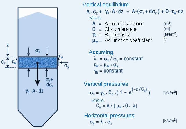
Around 1895, Janssen made a number of measurements at square wooden grain silos in which, with different filling heights,
the pressure on the flat bottom was determined with a scale.
Here, the measured bottom pressures were found to increase less than linearly with filling height.
With a sufficiently high silo, the bottom pressure never even exceeded a certain maximum value.
Modifications to silo theoryThe Janssen model was reasonably satisfactory until about 1950. But thereafter, the development of and better knowledge about structural materials and methods led to lower safety factors. This necessitated a more precise determination of the loads. It resulted in a multitude of theoretical and experimental research from which it soon became clear that the problem of silo loads was very complex and an exact solution would not come soon. The proposed solutions were always based on simplifications and sometimes simple approximations. All this work contributed to a better understanding of the problem. 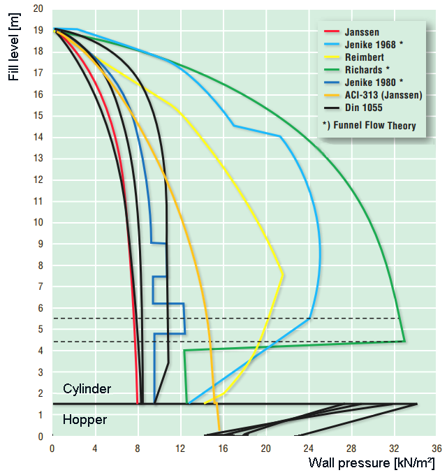
It was clear that differences existed between the filling and emptying situations, that the flow pattern affected the loads,
and that changes in the internal stress gradient, e.g. due to a change in cross-section or built-in elements,
could be accompanied by high, localised wall stresses. It was also recognised that due to the dynamic behaviour during outflow,
the stresses also showed large variations. These new insights lead to codes of practice and standards in many
countries that did not always prove easy to apply and, when compared, lead to rather different results.
Clearly, the choice of standard is a determining factor in the calculated wall load. Flow and wall loads
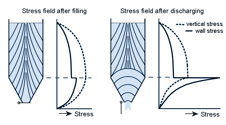
As mentioned, the classical Janssen formulas basically apply only to the filling situation.
During the filling of a silo, the bulk material will be somewhat compressed vertically due to the pressure of superimposed layers.
The greatest stress in this situation will therefore be vertically oriented, we then speak of an active stress field.
Now, when the outlet valve is opened or the unloading equipment started, and the bulk material starts flowing into the hopper,
a different situation arises. The bulk material will expand in a vertical direction,
and at the transition from cylinder to hopper it is compressed horizontally.
The largest stress adjusts to the deformation and will now be horizontal,
a so-called passive stress field.
This reversal from active to passive will start at the bottom of the funnel and continue until the transition to the cylinder.
In principle, a further reversal does not occur because bulk material in the cylinder does not need to deform.
So there is a transition area here. In this area, a substantial, localised peak pressure can occur on the wall,
starting at the bottom of the hopper and continuing as a continuous peak at the transition,
the so-called switch load.
These local peak stresses at the cylinder/hopper transition are usually not a problem for the silo structure,
as it is already stronger there due to its geometry, and is often reinforced, especially when the silo is supported by legs.
Silo standards
Several countries drafted silo standards over time to establish a uniform starting point to calculate silo loads.
For a long time, the German DIN 1055, part 6 was used across Europe.
This standard, first released in 1964 and based on Janssen's theory, distinguished between the filling and emptying situation and took into account the influence of an eccentric outlet.
The disadvantage was that the scope of application was limited to free-flowing and slightly cohesive materials.
In practice, however, many cohesive materials occur, and in the absence of other options, DIN 1055-6 was therefore applied to these as well.
Another objection to this standard was that the wall friction angle was not considered separately but calculated as part of the internal friction angle.
EuronormTo unify the multitude of calculation methods and standards in Europe, the first discussions for a European standard started in the late 1980s, within the body of the Eurocode. The Eurocode EN 1990 provides foundations of structural design, establishing the principles of requirements of safety, serviceability and durability of structures, defines the bases for their design, calculation, and testing, and provides guidance on related aspects of structural reliability. EN 1990 is intended to be used in conjunction with EN 1991 tm EN 1999. EN 1991 can be used to determine various loads (e.g. wind and earthquake), and this includes silo loads. These are dealt with in EN 1991-4; Eurocode 1: Actions on structures – Part 4: Silos and tanks Loads in silos according to the EuronormDiscussion of EN 1991-4Scope and limitations; Classification and design situations; Application of bulk properties; Measurement of wall friction, internal friction, bulk density, stress factor K; Calculation of loads; Conclusion IntroductionSince the early 1990s, a series of standards on loads on structures and building works has been worked on in a European context to unify the technical bases and safety requirements in the EU. This is the Euronorm, series EN 1990 - EN 1999. With EN 1991, a variety of loads (e.g. wind and earthquake) can be determined. For silo loads, EN 1991-4 Loads on structures; silos and storage tanks. This article discusses the calculation of silos. EN 1991-4
After a number of preliminary versions of standards on loads on structures and buildings were issued for comment in the 1990s,
a completely updated version was published in May 2006: EN 1991-4:2006.
There are three official versions of European standards: English, French and German. For the Netherlands, the English version will apply.
A note has been added in the first paragraph of this version: NOTE 1 Silos are used for the storage of particulate solids: tanks are used for the storage of liquids.
An open door for the bulk technologist (perhaps), but not so well known in practice.
Scope and limitationsThe standard will have to be applied in conjunction with the other Euronorms in the EN 1991 to EN 1999 series, which cover other aspects such as choice of materials and general safety requirements. The standard gives general guidance on determining loads for the strength and structural design of silos for the storage of bulk materials (particulate solids) and of tanks for the storage of liquids. In this article, we leave tanks aside and restrict ourselves to silos. 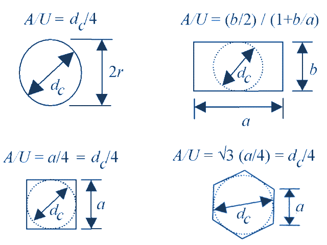
Application of the standard is limited in terms of geometry to:
There are also a number of requirements for the bulk material and use of the silo:
Finally, it also states that influences from earthquakes, internal shocks or vibrations are not covered by the standard. Nor can the standard be used to design a silo in terms of flow behaviour. The above limitations were also present in previous standards and are such that most silos can be calculated with the standard. It should be noted, however, that the properties of a lot of bulk materials are unknown. Another problem is that internal shocks, for instance, cannot be predicted in advance. Classification and design situationsWhen calculating the loads on a silo, according to the standard, the silo shape, the properties of the bulk material and the occurring flow pattern will have to be considered. In the standard, the pressure from the bulk material is built up from a symmetric and an asymmetric part (patch load). In case of large eccentricities, the total load is considered as non-symmetric. The standard further specifies a classification into safety classes (Action Assessment Classes) based on size and eccentricity. Silos with a storage capacity larger than 10,000 tonnes, or with large eccentricities fall under class 3. Silos with storage capacity less than 100 tonnes fall into class 1. The remaining silos are class 2. This classification is related to the general safety requirements for structures as laid down in standards EN 1992 and EN 1993.
The loads due to bulk material on a silo consist of normal and shear forces on the cylinder wall, hopper pressures and a maximum bottom load.
Parameters in the calculation are: the wall friction on the cylinder and hopper wall, the bulk density,
the internal friction, and the lateral tress factor K (thje ratio between horizontal and vertical pressures) of the bulk material.
Furthermore, the type of flow occurring in the silo is taken into account. A distinction is made between mass flow (plug flow), core flow (pipe flow/funnel flow) and mixed flow. For mixed and pipe flow, a further classification is made according to the degree of eccentricity. 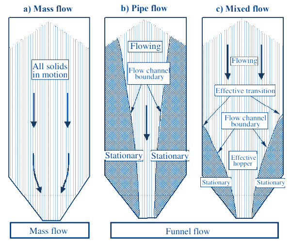
A further classification is that according to the shape of the silo, see picture below. Distinguished here are horizontal silos, where the walls act as a retaining wall, flat silos and slender to very slender silos, the latter with the possibility of channelling (ratholing) due to asymmetric filling. Finally, details such as pneumatic filling, air injection or internal mechanical spreading systems are considered. For all these categories, the standard specifies how the loads should be calculated. 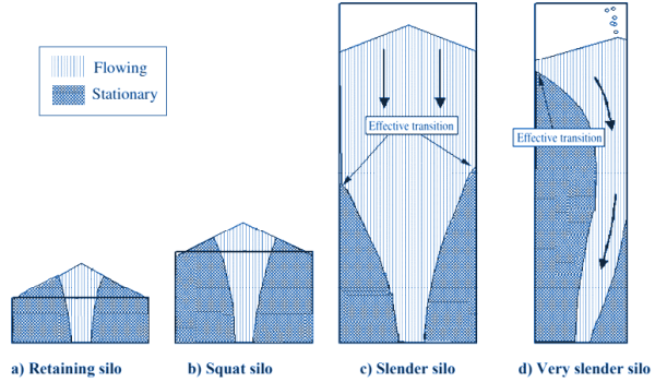
Application of bulk material properties
One difference from previous standards is the emphasis on the properties of the bulk material, and particularly on how to measure them.
The standard mentions two possibilities. The easiest way is to use the table given in Annex E, which lists the required values and surcharge factors for 24 types of bulk material.
This table also gives the data for a so-called default material, which can be used if the cost of testing the actual products cannot be properly justified.
Use of this ‘default material’ is only recommended for small silos, as larger silos do create very uneconomic designs.
For example, a bulk density 2200 kg per cubic metre is suggested, which is three to four times heavier than most types of feed or plastics.
Measuring wall frictionThe standard distinguishes four typical wall materials (Table 4.1):
The test method to be followed is described in Annex C of the standard and corresponds to a standard shear test. Emphasis is placed on measuring at the right pressures and at the representative wall material test plates. In the case of corrugated walls, for example, the wall friction can be calculated as a weighted average of measured wall friction and internal friction. Measuring internal friction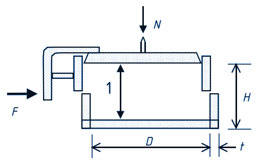
For measuring the internal friction, a ‘direct shear test’ is mentioned first. The standard pressure to be applied and the test method to be followed are indicated, to determine the internal friction and cohesion. A triaxial test may also be used. Alternatively, an ‘indirect measurement’ with the Jenike shear cell (with standardised measurement procedure according to ASTM D 6128) is given. This Jenike shear cell is exactly the tester as indicated for the direct shear test. The difference between the direct and indirect test thus seems to be the procedure used. Measuring bulk densityBulk density can be measured by loading the material in a cylinder that is not too high (diameter about twice the height) through a top lid and measuring the volume. Again, method and pressures to be applied are indicated. The Jenike shear cell meets the given dimensions, and the bulk density at different pressures becomes known when the bridging behaviour is measured. Measuring the lateral pressure ratio K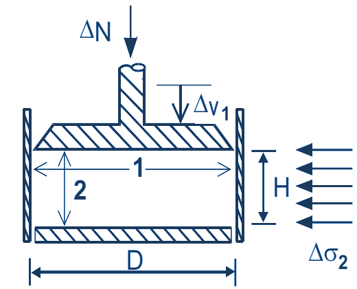
The factor K gives the ratio between the horizontal and vertical stresses in a silo. In principle, this factor can be measured with an apparatus as specified in the standard. In this apparatus, a bulk material sample is loaded vertically with a stress σ1 and the horizontal stress is measured. The latter is done by measuring the strain in the thin-walled cylinder with strain gauges. Clearly, this method for measuring K is now not directly simple. In fact, it is known from research at the University of Twente that a tester that can measure this is very difficult to make and the measurement itself is time-consuming and poorly reproducible. The result is a cloud of measurement points, so this factor might as well be estimated in some other way. Fortunately, the standard also recognises this. An approximate value of K can alternatively be calculated from the internal friction. Calculation of loadsOnce in possession of the correct data of the bulk material, all relevant silo loads can be calculated based on silo shape, size, flow pattern and possible special features. The standard details the calculation methods to be followed in almost all cases. In some cases, permissible alternatives are also given. Finally, for products where dust explosions may occur, a number of recommendations are given for the safest possible design. Conclusion
We conclude that this standard provides an adequate calculation method for determining silo loads for almost all common cases.
However, there are still some snags. First, using the standard is not exactly straightforward.
Partly due to the pursuit of completeness (the standard covers 163 pages!), the whole thing has become rather extensive and complex.
It is easy to lose your way in the maze of possibilities.
Furthermore, measuring bulk properties almost always seems unavoidable. Even for the 24 products given in the standard,
the type of flow must be known so that flow problems can be ruled out. With the data in the standard, little can be said about this.
Only experience with the product or through measurements more certainty can be obtained to this respect.
Loads on inserts in silos and bulk materialsInserts in silos and stockpiles are heavily loadedLoads on vertical rods and cables; horizontal elements; tie rods; other elements; Loads when pulling up inserts; Horizontal loads on vertical inserts, columns, pipes; Loads on intermediate cones, partitions; Influence of inserts on wall pressure in silos. Inserts
Inserts
Elements that are built into silos are called inserts. Inserts are used to favourably influence the flow of bulk material in the silo or to reduce
the pressure in the silo or the load on the discharge equipment. Another application of inserts are horizontal tie rods to support long silo walls.
Vertical rods or cables to hang measuring or recording equipment in the silo are also surrounded by bulk material and can be called inserts.
See functions of inserts.
Load on vertical rods and cables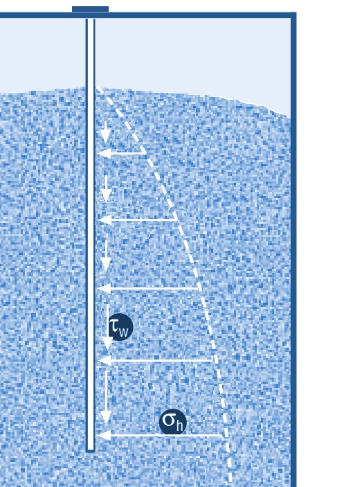
As long as the cable or rod is reasonably smooth, i.e. has no real ridges, a fairly simple situation arises.
Horizontal normal stress acts on this rod from the bulk material. This would want to dent the rod, but there is no danger of this happening.
In the vertical direction, the shear stress acts. This is equal to the horizontal normal stress multiplied by the friction between bulk material
and rod/cable and bulk material. Since the normal stress increases with depth, the shear stress along the length of the rod/cable will have
to be integrated to calculate the total vertical force on the rod.
As the stress increases with depth, twice as long rod will have to absorb a much more than twice as large vertical load.
Load on horizontal elements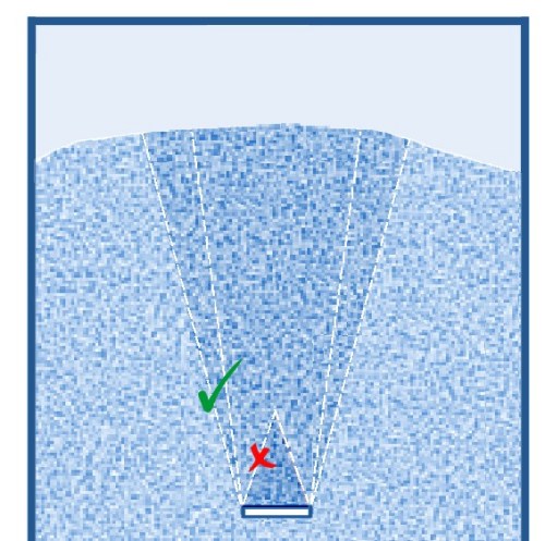
If the silo contains inserts with a certain surface area in the horizontal direction, the situation is a lot more complicated.
The element is now not only loaded vertically by friction but also experiences a vertical load from the bulk material above it.
This vertical load is considerably larger than one might expect. One often imagines a pile of product remaining on the element,
creating a roof shape where the bulk material flows past without putting too much load on the ‘roof’.
Load on horizontal tie rodsThe vertical load on a tie rod depends on the depth in the silo, the width and the shape of the rod. Because the rod gives a much larger disturbance in the material than just the horizontal support surface (see figure above), the silo pressure in situ must be multiplied by a factor. The background of this factor is this: already in the filling situation, the bulk material in the silo will collapse somewhat as the filling increases. At the location of the rod, however, no collapse is possible while the material around the rod does collapse somewhat. This creates additional friction on the material resting on the rod, thus increasing the vertical load. The extent to which this already occurs to a considerable extent in the filling situation depends on the settling of the bulk material and the silo pressure at that position. During emptying, there will always be movement along and around the bar with additional friction and thus increased loading.
The magnitude of the load on a surface in a bulk material has been experimentally investigated by several researchers and has led to rather different results and,
unfortunately, no unified calculation method. However, it has become clear that the value of the load on the bar becomes relatively larger with a smaller width.
The shape of the rod plays a role here: for round and diamond-shaped rods, the load is slightly lower than for rods with a flat top.
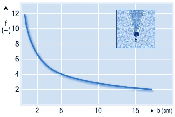
This graph is an estimate based on experimental research Loads on other elements built-in in a silo
For loads on other elements installed in the silo, consider built-in elements that must influence the flow,
such as wall-supported cones or hoppers or measuring equipment suspended from cables.
In principle, the loads here can be calculated in the same way as indicated above for tie rods.
Again, the load on the insert is much greater than the surface area and vertical silo pressure would suggest.
And again, a small insert will experience a relatively higher load.
In narrow silos this is even more true, as larger inserts will soon absorb the maximum pressure;
the entire cross-section times the silo pressure.
Load when pulling up inserts
A special case occurs when an insert is pulled up from the bulk material.
In many cases, the force required for this turns out to be even very much higher than the (increased) load indicated above.
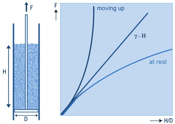
A simple experiment can make this clear. The figure below shows a cylinder containing a horizontal disc suspended from a cable or rope.
The diameter of the cylinder is slightly larger than the disc so that the latter can move through the cylinder without friction.
When bulk material is introduced into the cylinder, the disc will not bear the entire weight of the bulk material,
because the cylinder wall absorbs part of it through friction.
The force on the disc can be calculated using Janssen's standard silo formula.
When the disc is pulled up, the load on the disc will increase because now both the entire mass of bulk material has to be lifted, and on top of that the wall friction has to be overcome.
So the vertical load of the disc on the bulk material now increases.
But with this, the horizontal load also increases, because it depends on the vertical pressure via the stress ratio (factor K in EN 1991.4).
As a result, via wall friction, the vertical force also increases again. The force appears to increase exponentially with the material height.
With a low height of bulk material on the disc, it can still be moved upwards, but at a filling height of about 3 times the cylinder diameter, this is impossible.
Horizontal loads on vertical inserts
Vertical inserts present in a silo, for example in the form of relief pipes or mixing screws, are initially loaded vertically by shear forces due to horizontal pressure
and friction. These vertical forces can be calculated well using standard norm calculations so that the structure can withstand them.
In practice, it is asymmetric horizontal forces that cause the problems.
The horizontal pressure in a silo is never evenly distributed - as is the case with a liquid.
If a vertical column or pipe has more flow on one side, the local pressure can become much lower.
The result is a much higher pressure on one side, and the associated bending stresses.
Several times in the past, this has led to major damage to internal pipes.
To avoid these problems, it is wise to assume a full bulk pressure on one side of the pipe during dimensioning.
A magnification factor similar to that for tie rods must also be taken into account, see Fig. 3.
Loads on intermediate conesSometimes intermediate cones are fitted in the cylinder to limit the maximum pressure in the silo. For example, to reduce the risk of vibrations and shocks, or to limit their size. Another reason may be to keep the pressure on a pull-out mechanism sufficiently low. Such an intermediate cone will transfer a significant part of the vertical silo load on site to the cylinder. The connection between cone and cylinder will therefore have to be sufficiently strong. For the intermediate cone itself, one can assume the loads as described in the codes for a normal cone at the bottom of the cylinder. The cylinder is also loaded very differently by mounting an intermediate cone, because now a large vertical load must be carried locally. There will also be a peak in the wall pressure (see below). This must be borne in mind especially with thin-walled, buckling-sensitive designs. Loads on partitioning wallsAnother way of reducing pressure or preventing segregation is building in partitioning walls. The partitions can be calculated as normal silo walls with the applicable standard. The pressures on them will be lower than in an undivided silo, because the cell dimensions are now smaller. It must always be assumed that an intermediate wall is loaded horizontally from only one side. However, the shear stress on the partition should be taken into account on both sides. A possible supporting effect from the other side should not be included. Influence of inserts on wall pressure in silos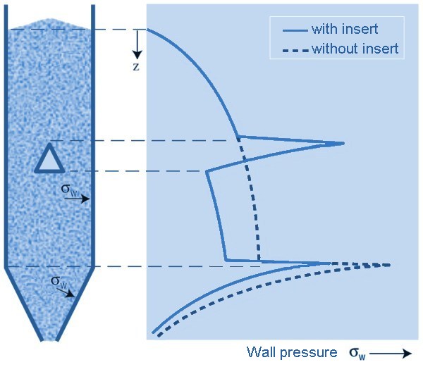
The load on inserts must be absorbed in the silo structure. This will usually be done on the silo wall at that position.
However, even when the insert is not supported by the wall, in most cases the wall will still be subject to a heavier load due to disruption of the flow.
This is the wall pressure: the pressure perpendicular to the wall (in the cylinder, this is the horizontal pressure).
ConclusionUnfortunately, there is no unified calculation method available to determine uneven loads due to flow disturbances. Based on proposals derived from experiments, often not more than a rough estimate is possible. Perhaps in the future, computer simulations in which flow and pressures around inserts can be calculated, will provide a more practically useful answer. |